I introduced OzPLAR in my previous post. It’s an evolution of the telephone intercom design I had published in Silicon Chip magazine back in 1992.
With my 2021 collaborator Ross we deliberately designed the circuit and PCB to accommodate a range of variations and alternate components so as to make it as flexible and globally-appealing as possible.
This page documents some of those variations.
Electronic battery feed
Back in the dark ages we used transformers to couple power from the exchange into a phone line. The transformers had a high impedance to speech, and so they were able to send power to the line whilst blocking the flow of speech through the battery. Without this high impedance the speech would be shunted to ground through the low impedance of the exchange’s battery, and none would make it to the phone line. Crosstalk between unrelated lines would also be expected.
Eventually this transformer was replaced by the “A” relay in a bimotional switch, and then when everything went electronic, ICs took over.
The 8-pin Lucent LB1011 solid-state battery feed IC is long obsolete, but good stocks are still available online, and so we’ve added this as an option to the OzPLAR. (I sourced mine from UTSource for $US0.93 + shipping, and I see you can even find them on eBay.)
Built in this variant the OzPLAR could be built for $AU30-50 cheaper than equivalent iron-core components, and with superior performance into disparate lines as each telephone gains its own self-contained battery feed.
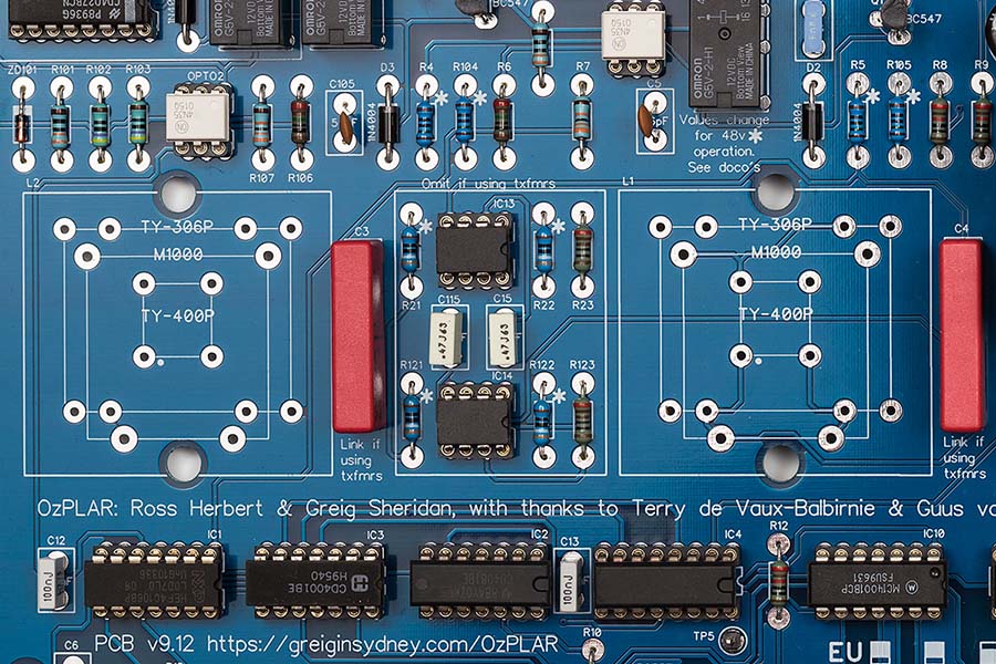
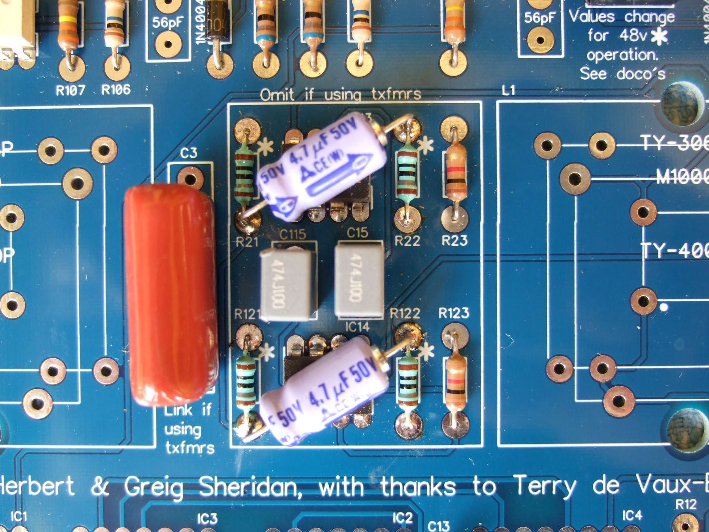
That tiny nest of components in the middle of the board is the battery feed, flanked by the space the two transformers would otherwise occupy:
Power supply ‘whistling’
We’ve noticed that the LB1011 seems susceptible to power supply noise from cheaper 24V switch-mode supplies, so if you end up with any whistling or what sounds like a high-pitched digital noise across the line, suspect your power supply in the first instance. From our testing, plugpack-style switch-mode power supplies are more susceptible than inline “line-lump” versions.
Our suggested cure is the addition of an inductor (like this one from Mouser) in series with the positive supply rail, and one or more electrolytic capacitors.
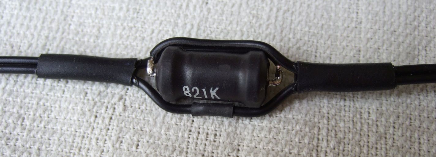
This image is of the inductor in-line, before being encased in heatshrink:
I found a 470uF 35V electro to ground on the intercom-side of the inductor would kill the bulk of the remaining noise, whilst Ross went for a 4.7uF electro across the supply rails of each of the ICs:
(Thanks to Ross for the images and diagnostic work.)
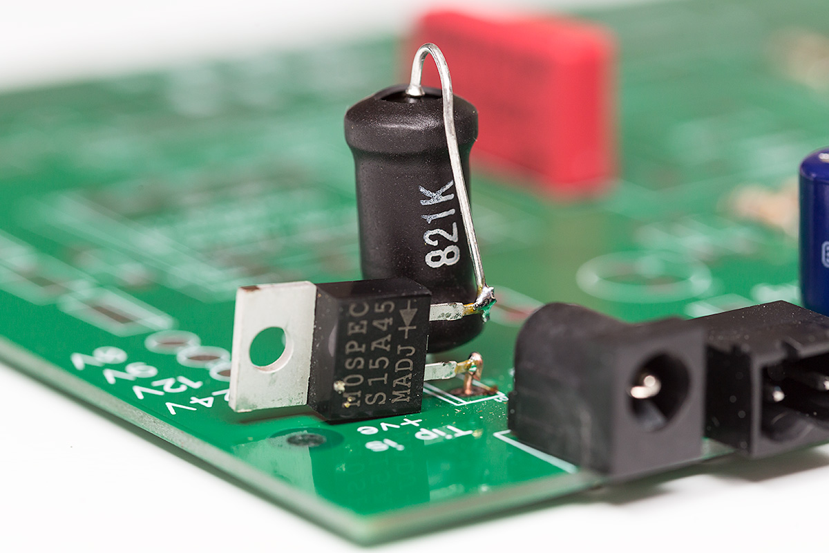
An alternative to installing the inductor inline is to remove the reverse-polarity protection diode D1 and reinstall it on its side, with the inductor now in series with it. The nearby 100uF capacitor (marked C9 on the PCB overlay) can be increased to 470uF or 1000uF.
Bespoke cadence creation
With simple link selection alone the board covers off a lot of the world, with the AU/NZ/UK, much of Europe and two US cadences all easily selectable:
- AU/NZ/UK 400mS on – 200ms off – 400ms on – 2s off
- Europe 1s on – 4s off
- US Short 1s on – 2s off
- US Long 2s on – 4s off
You can read more of the ‘cadences of the world’ in this ITU PDF.
Should you be looking for something more esoteric, provided your desired on/off times are multiples of 100ms then some links or flying leads should easily deliver.
As detailed in the magazine article, a 4017 decade counter provides 10 outputs that go high for 100ms at a time, and another daisy-chained 4017 provides ten that are high for whole seconds, up until the second 4017 resets – up to 10s in total. The associated logic determines the on and off periods, and how long the whole cycle takes before it repeats.
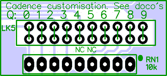
The 10 outputs of the first “units” 4017 are exposed on header LK5 to allow customisation, with pins marked CON7 and CON8 exposing the Q2 and Q4 outputs of the “tens” (whole seconds) 4017. The intent of exposing the latter pins is to allow you to reset the cycle for a total running time of 2 or 4 seconds respectively.
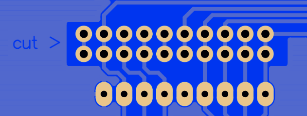
To access the bespoke functionality you’ll need to add the resistor network adjacent LK5 and optionally add LK5 itself, a 2×10 strip of header pins. An essential step – certainly required before soldering LK5 – is to cut (on the under-side of the board) the tracks that run down the centre of its two rows of pins, as those tie the relevant 4017 outputs to the 4078 OR/NOR gate to generate the default AU/NZ/UK cadence selection.
This is a view of the under-side of the PCB, showing the word “cut” etched into the copper, pointing to the centre of LK5’s pins:
On bursts
With JP1, JP2 and JP3 set for “AU”, linking the required LK5 outputs will build a cadence in 100ms increments. (Note that the 8 inputs of the 4078 limit your cadence to a maximum of 800ms of “on” bursts.)
The top row of pins are the 10 x 100ms pulses, and the bottom row are simply 8 inputs to the OR/NOR gate. As such the middle two pins on the bottom row of LK5 are not connected, as denoted by the “NC” on the silk-screen overlay:
Silence between repeats
The setting of JP3 will vary the silent time between cycles. Link the centre pin of JP3 with:
- JP2 pin 1 for a total cycle of 1s
- CON7 for a total cycle of 2s
- JP3 pin 3 for a total cycle of 3s
- CON8 for a total cycle of 4s
- JP3 pin 1 for a total cycle of 5s
Leave JP3 unlinked and remove/omit diode D4 for a total cycle of 10s.
Sample cadence
Here’s a view of a board strapped to generate a cadence of three bursts of 200ms on with 200ms between them, followed by 3s of silence. (Remember it’s the top row that are significant here).

(Click on the image to view it full-size.)
Those yellow links are the Pololu 3304, which I buy here in Oz from RobotGear.
Here’s what it looks like on my Saleae logic analyser, with the bottom trace being the ultimate cadence:

Taking it further
If you’d like your on-bursts of the cadence to extend over *two* seconds, set JP2 for “US-Long” and link the appropriate outputs in LK5. Note that this will result in the same “first second” of ring repeated twice per cycle, granting you even more flexibility in bespoke cadence selection.
Revision History
4th December 2021. Added text and images re power supply whistling.
27th September 2021. Published publicly.
30th August 2021. Minor cleanup.
– G.


Hi, I was just wondering if the currently available boards happen to include the inductor and cap updates, or should I expect to bodge them on?
Hi David,
You’d need to confirm that with Silicon Chip as they’re producing the boards, but I suspect they’re still shipping the as-published version.
Note that those extra components are only required to workaround the shortcomings of some cheaper switch-mode power supplies and then only when built with the LB1011 battery feed, and aren’t always required. If you’re untrusting of your supply, I’d suggest assembling the board with D1 temporarily on fly-leads and a larger C9 (as mentioned and photographed above), then retrofit the choke and other electros if they turn out to be required, and if not, D1 can go back into its original holes.
– Greig.