If you’re new to the “DHMG” – our annual housewarming party – and its attendant excuse for some crazy home-brew tech, there’s some back-story and an index of the things we’ve done here.
This is part 1 of a 2-part series covering 2019’s “Disco Death Star”:
Part 1 – The Build – construction and assembly – this post
Part 2 – Control, programming & examples
The Lead-up
At some stage in around April each year we realise it’s 12 weeks until our annual party (nowadays always the last Saturday in July), and we madly thrash around in some kind of panic state until we come up with an idea for “the effect”. This year was no different.
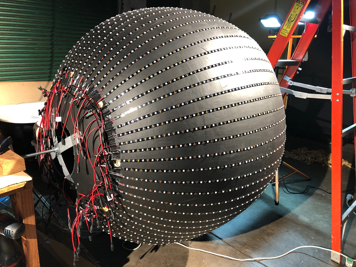
The concept we settled on was a large ball COVERED with as many individually-addressable RGB LEDs as could fit onto it: like a giant self-illuminating mirror ball.
We’ve used RGB strip LEDs before, but only the 4-wire ones where the whole strip is the one colour. This time we needed to take the plunge to the “WS2811” family and its derivatives.
Having committed to the idea, the build commenced with two parallel streams: the construction of the ball, and all of the electronics we were going to adorn it with.
Building the Ball
I shopped around for big hollow balls and drew a blank. That left us with the default position of covering a beach ball with papier-mache.
Having sourced and inflated the ball, the first fear set in. This thing is HUGE! I probably coulda gone with the next size down. Oh well, too late for that.
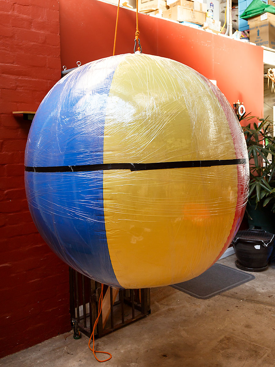
In preparation for papier-mache, we covered the ball with a few layers of cling-film. This was to ensure we could easily deflate and remove the ball later. The black gaffa tape around the middle is just to keep the cling-film in place until we had some layers of paper over it.
The internet suggested we use either a glue made of flour, or alternatively PVA glue, and given our more industrial intent we opted for the latter. The whole ball took around 8 Litres of PVA, diluted in a 3:1 ratio with water.
Luckily for us some of our more elderly neighbours still buy newspapers, so a bit of domestic dumpster-diving over several weeks provided the other required raw material.
We were only a layer or two in when we noticed some cracks in the ball. This was as a result of the air inside the ball expanding and contracting between the warmest peaks of our winter days and what we Sydney-siders consider the freezing depths of night. It was with some relief that that stage seemed to pass without causing any problems.
We ended up layering the ball with 20 layers of paper, and the resulting crust is maybe 8mm thick. Each layer was applied in two sessions, with the top (or bottom) half going on first, let to dry a little, then the ball gently inverted and the rest of the layer applied. Each of those 20 layers took between 3 to 4 hours to apply, so we’re talking 2 solid person-weeks of gooey crafting (all the while trying to keep the cats out of the splash zone underneath).

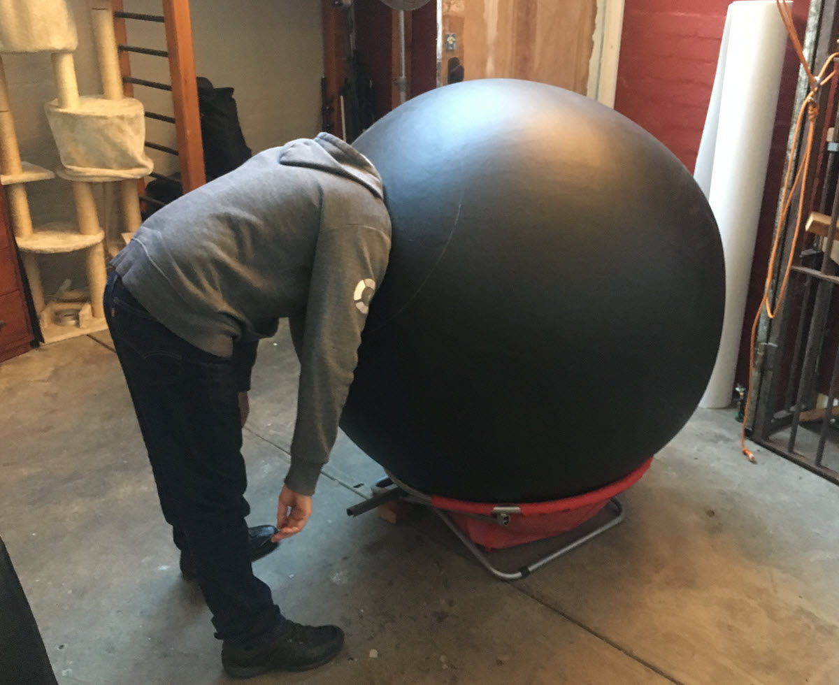
Thankfully it came out looking spherical – although the layer of matt black paint helps that effect. (BTW, we deliberately added extra paper at the very top and bottom of each layer to add extra strength at the critical load-bearing points.)
Once we’d decided we were done, a hole was drilled near the top to puncture the ball, then after it deflated a little naturally we enlarged it so we could get to the inflation point and attach the vacuum. It didn’t take long to remove all the air and fish the ball out.
Here’s Rocky modelling it.
LEDS & the Electronics
While all the papering was taking place, the serious bits of the electronics were sourced and prepared.
WS2812B LEDs
I got off to a false start here and learnt a lesson in the process. Lots of eBay vendors seem to deliberately list their LEDs as “WS2811 / WS2812B”, quote the price for the cheaper one (the 2811), and play upon the inexperience of n00bs. Ouch. Insert ~2 week delay here.
I had set my heart on using 12V LEDs so I had less current to deal with on the ball, and thus lower power losses. Alas, it turns out that WS2811 runs on 12V, but has three discrete LEDs per ‘pixel’ (addressable channel), resulting in what would be an unacceptable loss of resolution on the ball.
That forced me back to the 5V WS2812B, where each little white LED square is truly individually addressable.
WS2812B is available in 3 LED densities: 30, 60 or 144/150 LEDs per metre. The more LEDs the higher the ball’s resolution, but with the added extra procurement cost, increased power consumption and driving complexity.
I settled on the 30LEDs/m variant. Its ~3cm LED spacing meant I could space the columns 3cm apart around the ball and have each LED roughly equally spaced.
Given the diameter of the ball, that came out to 64 columns, a fortuitous figure we’d only appreciate the value of the week before the party. (More on that in “Final Assembly”, below, and in the next post’s “Lessons Learnt”.)
Some research online ‘led’ me (sorry) to vendor “Chinly”, and I bought TWENTY 5m rolls of the 30 LEDs/metre, non-waterproof configuration.
While I waited for them to arrive from China, I built a “test ball”, using a 5m roll of WS2812B’s @ 60 LEDs/m that I horse-traded with my eBay vendor after the WS2811 fiasco. I wrapped 16 strings of 16 LEDs around a piece of PVC downpipe to become my test rig. I was working away from home each week during this period, so I was able to pack the test ball in my luggage and set it up in my hotel room, trying to figure out how to code it at night. I honestly expected to be paged in the airport lounge the first day I flew with it, figuring it to have set the luggage X-ray machine into apoplexy, but I guess our domestic checked luggage isn’t scanned…

FastLED
The magic behind all this is the FastLED project, a “Fast, easy LED library for Arduino”. I’m truly in awe of this community and what they’ve been able to create.
Part of the reason behind these two posts, and the videos of what I’ve been able to create with FastLED and OctoWS2811 is my way of paying back the contributions of all those without whom we wouldn’t have been able to pull this off – and of course to show the authors of the patterns I used what they look like when rendered on several thousand LEDs.
I digested what I could and decided on a parallel drive setup, where 8 IO pins would operate in tandem, each driving 12.5% of the ball’s LEDs. I figured that would be able to drive them fast enough for my purposes. I was in for a nasty surprise.
Cartesian Maths & a Serpentine Setup
Despite the spherical nature of our creation, I’d always envisaged the LEDs as a flat Cartesian arrangement, simply wrapped around the ball. Viewed flat, the top left LED was at xy co-ordinates 0,0 and the last one was 63,44.
As far as the FastLED code’s concerned though, this ball is one 96 meter length of LEDs laid end-to-end. The first pixel is LED 0, and the last one is LED 2879.
It made the plans a lot easier when I realised that plenty of people have made “panels” of LEDs like this and conceived of the “Serpentine” setup where each alternate row of LEDs faces the other direction. You tell the code how many strips you have and how many LEDs are on a strip, and a function in the code decides if the LED you’re addressing is in an even or odd column/row (depending on your perspective/layout), and if it’s an odd row it “flips” the number of the LED in the strip (where the “first” becomes the “last”, etc) so that the correct one is lit.
Here’s the concept graphically, using an image borrowed from the OctoWS2811 website, edited and rotated 90-degrees to reflect my layout:
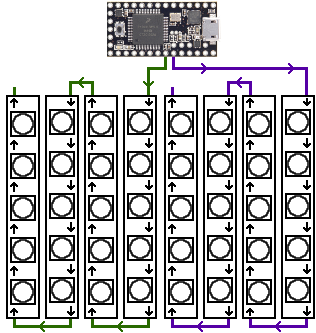
Each of my strips has 45 LEDs on it, and there are 8 strips per IO pin.
With this working, much of what’s written – and certainly all my fairly simple routines – are a matter of an outer x loop and an inner y loop taking care of what we’re going to light.
Teensy 3.6
With the “how many LEDs can I drive” question having a “piece of string” answer, I decided early on that I’d throw everything I could at this, and I made several lucky guesses that thankfully paid off.
I’d looked into high-powered Arduino-compatible devices recently for another project, so I was aware of the Teensy family.
The latest-and-greatest Teensy is the “Teensy 3.6“, which sports a 32 bit ARM Cortex-M4 processor ticking along at the seemingly blinding 180MHz! The 3.6 doesn’t seem to be supported (by any documentation I could find), but its precursors were, so I rationalised it was the doco not up-to-date rather than a technical limitation, and took the plunge. Or tried to.
It turns out that the 3.6 is in short supply. So short in fact that someone managed to snaffle the 2 out of my online shopping cart between me clicking “add” and making it to the checkout. Thankfully my Plan B – littlebirdelectronics (my new Plan A) had stock, and were able to get a pair to me quick-time.
Note that the Teensy’s IO pins operate at 3.6V and the LEDs run on 5V, so you’ll need a 74HCT245 to do the voltage conversion. I was to have my OctoWS2811 realisation a little later in the piece, and so at this stage I bought one of Jason’s level shifter PCBs, and then set about interfacing it to the Teensy. With the benefit of hindsight I now realise that I’d basically just built an OctoWS2811 Adapter the hard way. Ouch.
Power
With the LEDs on order I needed to find a power supply. Each LED pixel contains 3 discrete LEDs (red, green and blue), and each of those can draw 20mA. Decide you want a given pixel white – which you get by turning all three on – and you’re talking 3 x 20mA = 60mA, aka 0.06Amps.
THEORETICALLY, if I was to turn the ENTIRE ball white at full intensity, I’m going to need to find 2880 x 0.06A = 172.8A @ 5V. I decided that I will never let this happen, and compromised down to a situation where I’d power the ball with 3 x 40A power supplies, which should leave me plenty in reserve.
Now came the eBay fiasco.
I swear all of the sellers of LED power supplies on eBay in Australia are the same vendor, selling the same rubbish stock, to which they fail to add any packing and which will nearly always arrive damaged two weeks later (so much for “local stock”).
Here are two examples: the first is just one of the several supplies that arrived crushed or with a broken PCB. The box you see is the one it was shipped in. Not a dot of bubble-wrap to be seen anywhere.
The second is a supply that arrived with a very prominent rattle, which turned out to be one of its large storage capacitors floating freely inside. Imagine our surprise to find that this “new” power supply is repaired stock, and this unit has had such a catastrophic failure in the past it’s vapourised part of the track, necessitating the addition of the black wire in the repair.
 |
 |
Others – replacements, re-orders from another seller but probably an alias of the same merchant – arrived with slightly less damage, but signs of tarnish that only reinforced my belief that these were all reject or repaired stock.
Having lost trust and with time running out, I abandoned the lot – and eBay – and went in search of “proper” supplies online.
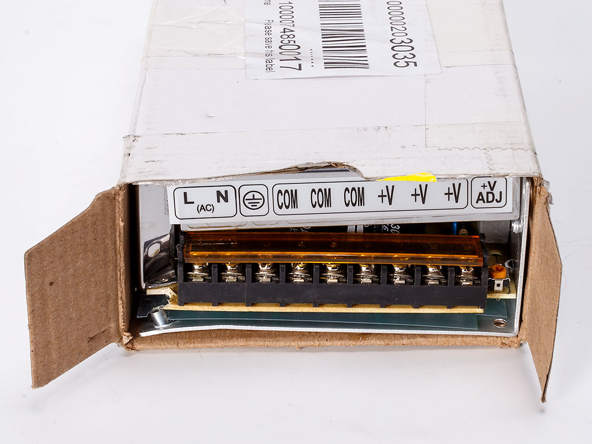
I was lucky enough to find Power Supplies Australia, who sold me a pair of solid 60A “MEAN-WELL-LRS-350-5” supplies that I have a great deal more trust in. Oh, and they ship them well-packed. I can’t thank these people enough for rescuing the project at this late stage.
I don’t have a proper photo of the final power ‘board’, but you can see it sitting on the bench in the final image in this post.
The two supplies are each mounted on a piece of plywood, back-to-back with a piece of ~3cm pine through which an 8mm hole has been drilled. The power supply assembly then slides down the shaft and is held in place with more locking nuts. A mains cable comes out of the central hole, as do 46 short leads to which each of the LED strips plug. The 2 extras I used to power the Teensy and for a utility “power-on” indicator LED. A weakness of this setup is that the power-on LED is only monitoring one supply and should the “wrong” one shutdown through an accidental overload, it’ll take out the Teensy and thus the whole ball. Ideally your Teensy will be powered by an independent 5V source.
Final Assembly
I mentioned earlier that deciding on 64 strips on the ball turned out to be a magic number, as it let us nicely divide the ball in half over and over again.
We started with the ball upright, and used a laser leveller we happened to have here to mark a vertical line on the ball. We then rotated it 180° (confirmed with a cloth tape measure) and made another vertical line, then rotated it another 90° – halfway between the existing lines – and repeated the process until we had 4 vertical ‘bearings’ from which point we’d keep dividing the ball in half.
From here we moved the ball to a horizontal position so the strips could be applied.
Each LED strip had been previously terminated with a power lead to make for easier connection and debugging. 32 of those have the power fed at the “top” (“signal in” end) and 32 are the other way ’round. (Refer the serpentine layout drawing earlier.) Eight were deemed the first in each string, so had a long wire attached to take their feed from the Teensy, and all bar eight (the end strip in each group) had a short data wire that I would later solder to its neighbour to loop the data circuit through. Having done all of this in advance made the task of getting the strips on the ball a lot easier.
We mounted the first four following the lines we’d made before, using the cloth tape measure to double-check the alignment before we peeled the covering off the adhesive backing. (It’s definitely a 2-person job).
From here on in all we did was divide the ball in half each time with the tape measure, adding a new strip at the mid-point between two strips. We measured at the top, middle and bottom of each strip before committing it to its final position with the adhesive.
Here’s Chip surveying our work while we paused for a dinner break at the half-way point:

32 strips in – all facing the same way – we’d divided the ball into an even number of slices, and we were left with 32 gaps. That then meant we could layer the next 32 in the other direction, each mid-way between the first lot. (If you look at the image above you’ll find no data tails visible. The first 32 strips were the “down” strips, so all the tails are at the other end.)
Here’s the ball, mounted “spit-roast style” after we’ve finished sticking the strips to it. Its central shaft is 8mm threaded steel rod, with the papier mache at the bottom (the ladder end in this image) sandwiched between two circular metal plates providing a relatively large surface over which to spread the load, and at the top with the criss-cross of gal strapping, also with matching pieces of strapping on the inside of each 3/16″ screw.
With all strips placed and checked it was a relatively simple matter of soldering the data tails at the end of each strip to its neighbour… and the smoke test.
Powering it up
I’ll confess now that that I wasn’t so bold as to throw the switch and pray. There was too much at stake for that.
I made a little test rig with a random 5W resistor (10 ohms) in series between a 2.5mm plug and socket. Across the resistor I clipped the multi-meter set to read volts, and I plugged in each strip in turn, looking at the voltage dropped across the resistor. Each read something like 200mV, which I decided was OK. That was just providing an indication of the ambient/quiescent current drawn by the strip, and indicated no fault. If the voltmeter had read 5V or anywhere near that, it would have meant there was a short on that strip that needed to be investigated.
With the strips deemed OK, *then* it was the time for the smoke test. Success!
I then did a quick logic test, feeding a single IO pin into each of the 8 “slices”. Each lit 8 strips, so we were good to go.
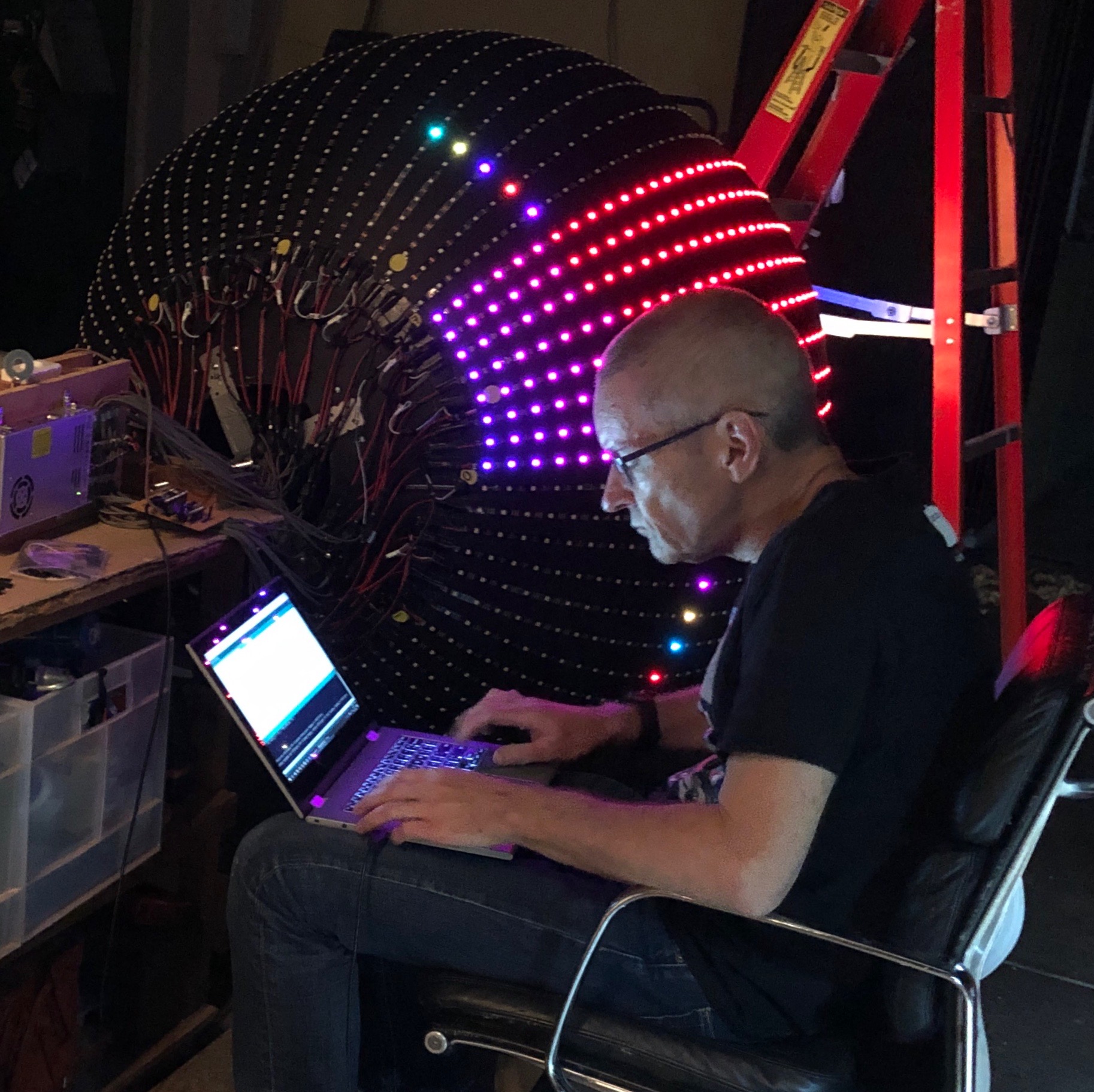
From this point in I could focus on the programming, but that’s a story for Part 2.
References / Research
If you’re still contemplating such a project, here are some resources that will hopefully smooth some of the bumps out of that learning curve:
- I wish I’d seen this 15 minute YouTube video explaining the difference with the LED string versions before I’d embarked on this project, not after I’d completed it.
- FastLED (Github)
- FastLED (Reddit site)
- OctoWS2811 LED Library
Jump to Part 2 where I show some code, link to the GitHub Repo that hosts the ball’s code, and the videos of it in action.
Revision History
31st December 2019. This is the initial publication, back-dated in the blog’s timeline to July 27th.
– G.


