In the process of migrating a customer to Lync recently we inherited an obligation to provide a *BIG* Message Waiting Indicator (MWI) light whenever a voicemail message arrived in a particular high-priority mailbox. That inspired me to embark on a campaign to see how many ways I could bring an external MWI light to reality.
Mucking with MWI – Part I uses a scheduled PowerShell script to query MWI and light a Blynclight.
Mucking with MWI – Part II is this post. Here we use the MWI LED in a CX600 to drive a mains-powered light through an optically-isolated solid-state relay (herein “SSR”).
Do I or Don’t I?
There are some pros and cons to this that we need to document:
Pros
- Easy to do – the CX600 was cracked and modded in under 10 minutes. Easy peasy!
- Relatively cheap to implement
- Flexible. Use any suitable solid-state relay and drive any mains load that it’s rated for
- Safe. Provided you do it properly of course, the mains isn’t at risk of coming into contact with the phone’s electrics
- Unplug the SSR from the phone and the phone’s LED still works like normal
Cons
- You need a phone, and it needs to be always signed-in as the relevant user
- You’re going to void the phone’s warranty the moment you pop the case
- Supportability might be an issue for you. It’s requiring a modified phone and some non-standard hardware that your average UC consultancy or customer isn’t going to keep handy
- Potentially fragile. If you hide the phone away under a bench you won’t actually know if the phone or SSR become unplugged or the user’s signed out
A Video Demo
Here’s a quick demo of the solution:
The Circuit
There’s nothing to it. All we’re doing is extending the phone’s MWI LED so that the LED in the SSR is added in series. When one lights, so does the other.
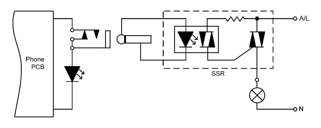
Why not in Parallel?
Being techy himself, Glen asked me why I went with a serial approach over wiring the LEDs in parallel. There’s no right or wrong answer to this one, but without knowing what was driving the phone’s LED, I thought running them in series would be more friendly to the phone’s electrics. This results in a slight reduction in brightness of the phone’s LED, and you can see the difference in the video when I unplug the SSR from the phone – the intensity of the phone’s LED jumps up. A serial connection also covers us if – as in the case of the AudioCodes – the LED in the phone is blue. Blue LEDs require a higher voltage to light, and if we paralleled a red LED across the blue there’d be the risk the blue one would no longer illuminate.
Building it
Finding the most suitable phone to use turned out to be the hardest part. I took apart most of the phones I had here at home and in the end it was the CX600 that stood out as being by far the easiest to mod. (The others I’ve detailed below).
Ingredients
- Your preferred phone. In this demo that’s a CX600
- Approx 4-6” (10-15cm) of light-duty 2-core hookup wire or ribbon cable. This will run from the phone to the socket we’re going to mount in the body
- An 1/8” (3.5mm) mono panel-mounting socket, with internal switch. The switch is crucial to ensuring the phone’s MWI LED will still light if you unplug the SSR
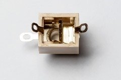
Don’t go overboard here and choose a 1/4” (6.35mm) socket – you’ll have problems fitting it in the phone - A matching plug for the socket
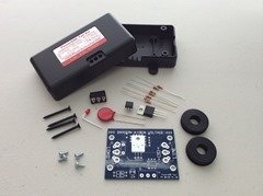
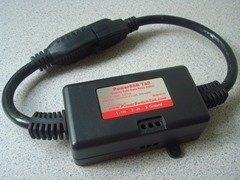
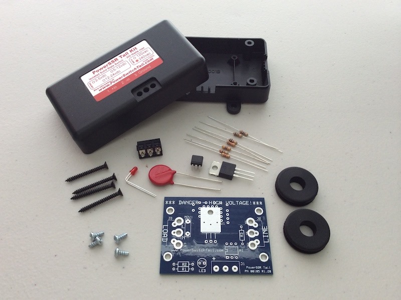
- A solid-state relay that presents only a LED (without voltage-dropping resistors) for its trigger. In my demo I’m using a 240V “PowerSSR Tail” (US$14.99 + shipping) that I built from a kit.
If you’re in the US or other 110V market you might like their pre-built PowerSSR Tail (US$19.99 + shipping) – although I’ve not tested this & can’t find its circuitAlas, they’ve since confirmed that all their pre-assembled versions include a voltage dropping resistor, so you either have to crack one open and bypass the resistor, build the kit version and omit it, or source another kind.
- If you’re building the PowerSSR kit, you’ll need some mains cabling between the supply and your light. I cut a 1m mains extension lead in half and used that. The benefit here is that the plug and socket ends are nicely moulded to the cable
- Some light-duty 2-core flex (say 3’ / 1m) to run from the phone to the SSR. If your plan is to leave the phone on the desk and bury the electrics underneath, perhaps double this length
- Soldering iron, solder, cutters, small Phillips-head screwdriver, drill, drill-bits, insulation tape


Method
- Sign the phone in and send that user a voicemail message. Confirm the LED lights on arrival of the message and extinguishes after it’s been listened-to. OK, we have a baseline – we know it used to work before you started!
- Disconnect all cables from the phone
- Unscrew the 6 case screws. Put them somewhere you’re not going to lose them
- The phone should come apart in two pieces. Take it slowly here as the speaker is actually mounted in the base. Thankfully it plugs in so you can unplug it to separate the phone halves
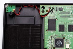
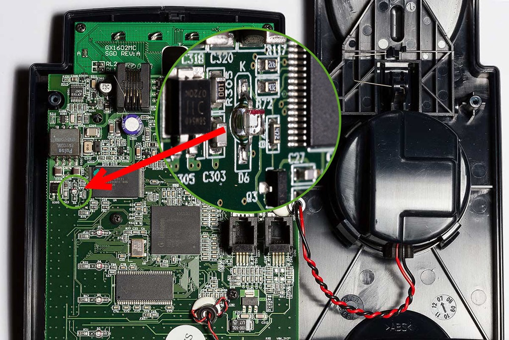
- With the phone resting face-down on a cushion or some bubble-wrap you’ll see the MWI LED on a small PCB, connected back to the main board with black and red wires. (If yours aren’t black and red don’t worry – the colour’s not important)
- I used a soldering iron to lift the black wire from its pad, soldering one end of the hookup wire to the pad and the other end of the wire to the now floating black wire. Insulate the join. If you’re not comfortable soldering onto the board (or your iron has too big a tip or poor temperature control), simply cut the red or black wire mid-span, strip some insulation and splice the hookup wire into the break.Click on these Before and After images for higher-res views:
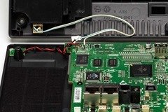
- Solder the socket to the other end of the hookup wire. Bridge the ‘switch’ tag to the ‘sleeve’ tag so that the socket presents a short-circuit when nothing’s plugged in. For the socket shown in the Ingredients list, that means the two left-hand tags are shorted together. Test this with a multimeter if in doubt.
- Locate a suitable place on the rear of the phone for the socket. I found there’s a good gap at the top rear. (Refer the RH photo above)
- Drill a small hole, then gradually increase the size of the drill-bit until it’s the right-size for the socket. (Mine ended up 15/64”)
- Mount the socket and reassemble the phone, checking to make sure the socket and its pins aren’t going to contact anything internally. Check the cable isn’t also going to get in the way
- At this point you can re-power the phone and repeat the test in step 1. The LED should still be lighting OK – if not, refer to Troubleshooting
- Solder the flex to the 1/8” plug and strip the other ends in preparation for the SSR. If you connect the plug to the phone with the MWI LED lit it should go out, but re-light if you short the free ends of the cable together. This proves all your soldering and wiring is good to the end of the flex
- Now connect the free end of the flex to your SSR. If you plug the other end into the phone and apply power, your mains light should follow the status of the LED on the phone. If not, reverse the polarity to the SSR and try again
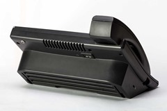
- Tada:


Troubleshooting
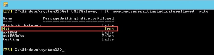
- If the prep test in Step 1 failed, check that the *only* UM IP Gateway in Exchange set with MWI enabled is Lync:
Get-UMIPGateway | ft Name,MessageWaitingIndicatorAllowed -auto
- If the phone’s MWI lights but the mains light doesn’t, you might have gotten the pin connections wrong on the socket. (The SSR is plugged in and you know the lamp you’re using is good, right?)
- If nothing lights, you might still have gotten the pins wrong on the socket, have bad joins internal to the phone, or the polarity to the SSR is the wrong way ‘round. There are two quick checks here: disconnect the two wires at the SSR and short them together. If the wiring’s good to that point the phone’s MWI LED will light. If that’s the case, just reconnect the wires to the SSR the other way around and brightness should ensue
- If nothing lights and your cabling checks out OK in the step above, it might be that your SSR device isn’t presenting a LED to the phone. Check its circuit or ask the vendor. If it has an internal voltage dropping resistor or is marked as being designed for 5 or 12V operation it’s unlikely to work without a separate power supply or modifications
- If the phone’s MWI LED doesn’t light when the SSR cable is unplugged, you’ve gotten the pin connections wrong on the socket
Alternate Phone Choices
I tried a few others but only the AudioCodes 420HD and Polycom VVX 410 appear to make the cut – and then only if you practice micro-surgery in your spare time. The most suitable phones appear to be those with a separate MWI LED and not one that’s a part of a switch or buried in amongst the keypad.
Snom 300
I had an old Snom 300 here but the LED wouldn’t light at all – not even when power was applied and every other LED lit. I don’t know if my phone’s faulty or if it’s too old to support this feature. It’s a shame as it’s a cheap phone and the LED is easy to get to: it’s mounted on the rear of the PCB, poking through a hole in the board to shine forward. (Click the image for a larger version).
Snom 700
I thought the Snom 700 had promise, but as I researched it I found that the big LED in the top corner *can’t* be used as an MWI light. This annoyed me as it’s REALLY easy to get to it and its wiring. Not to be deterred I refocussed my attentions on the mid-mounted Message button, but upon closer inspection realised it was going to take some doing – and I wasn’t game. The LED’s in a switch that’s on the front-facing side of the board, and I honestly doubted I could get it all back together after and still have the switch functioning and LED visible. If you have a spare you’re willing to sacrifice, take it for a whirl and let me know how you go. Send pictures. :-)
AudioCodes 420HD
The blue MWI LED on this guy drew me in like a moth to a flame. Remove the five screws and then with the phone face-up use a jeweller’s screwdriver or thin knife at the mid-point of each side to tease the snap-together clips apart. Be careful here as the headset socket and handsfree mike are mounted in the rear half by short cables. Both can be gently eased out of their mounts to free the two halves of the phone. With a good eye and SMD-capable soldering iron you should be able to de-solder the LED without further disassembly. I suggest you remove it entirely then reinstate it rotated through 60-90 degrees. With one leg on the board that will give you easy access to the other solder pad and to the free leg of the LED, whilst still letting the LED shine through the opaque part of the casing.

Polycom CX200 / “Catalina”
It took more time to remove all *9* screws holding the Catalina together than it did to dismiss it as too hard. The tiny MWI LED in this is part of the sandwich of buttons held to the face of the device by the PCB. Even if you *could* get it apart and back together again so that the buttons still worked, you’d have a hell of a time re-routing tiny wires to the back for the socket. Only for the determined or those with Olympic-grade stubbornness.
Polycom VVX 410
Eight screws gets you into the VVX 410 and the back pops off. (There are two hidden in the foot-stand slots). It looks do-able as well, with the same micro-surgery approach as per the AudioCodes. A few notes here before you start though: the LED winks at you in normal operation. That might be a good thing or a bad thing. Also, be careful to disable the power-saving LED otherwise you’ll get false indicators of MWI when the phone goes to sleep. A recent comment on my “Optimising the VVX for Lync” post gives that config element.
Have I missed any? Let me know if you have any questions or concerns.
– Greig.


