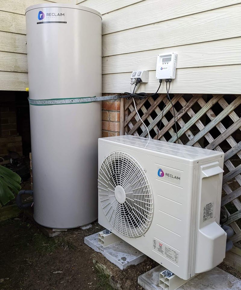
Our old hot water system died recently, and we jumped at the opportunity to replace it with a new Heat Pump unit, specifically the Reclaim.
The Reclaim is one of the most expensive in the market here in Oz, but it offers a very high COP and uses CO2 as a refrigerant, making it incredibly efficient and very ‘green’. Another selling factor is that it’s very quiet to run, which is an important consideration given how close it is to our neighbours. The low noise rating also makes it compliant with the NSW Government’s strict regulations that apply to heat pumps:
2.46B Development standards
The standards specified for that development are that the development must:
(a) not be a solar hot water system, and
(a1) if it uses a heat pump water heater, be designed so as not to operate:
(i) during peak time—at a noise level that is more than 5 dB(A) above the ambient background noise level measured at any property boundary, or
(ii) during off peak time—at a noise level that is audible in habitable rooms of adjoining residences, and
I also also very keen to get a model I could micro-manage, and by that I mean in some way integrate with our Home Automation, with a view to maximising our solar generation and minimising export. That might take a while to materialise, because the API isn’t due to land until 2024. But I’m getting ahead of myself. That’s not what this post’s about.
Your usual install
[Image credit, Facebook’s “My Efficient Electric Home (MEEH)” group.]
Most photos you see have the controller mounted outside. I wasn’t keen on that for a range of reasons:
- It’s not secure.
- You can’t easily get to it in the cold/dark/rain if you want to check its state or give it a Boost [mode].
- Importantly for the v2 model – it might not get a good enough WiFi signal through one or more layers of brick.
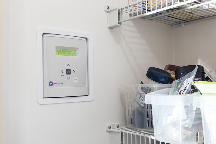
Our install
So our controller was always going to be mounted inside. Conveniently for us the kitchen pantry is on the wall opposite the hot water system, and that seemed a VERY practical place for it.
The Reclaim has two cables tethering the v2 controller to the external components: one for a temperature sensor in the tank and a Modbus cable to the ‘compressor’. Thankfully Reclaim offers those in 15m long versions, which was more than enough. (Note these are additional extras.) The controller also requires a power point / GPO for its power, which our local sparkies were able to provision nearby.
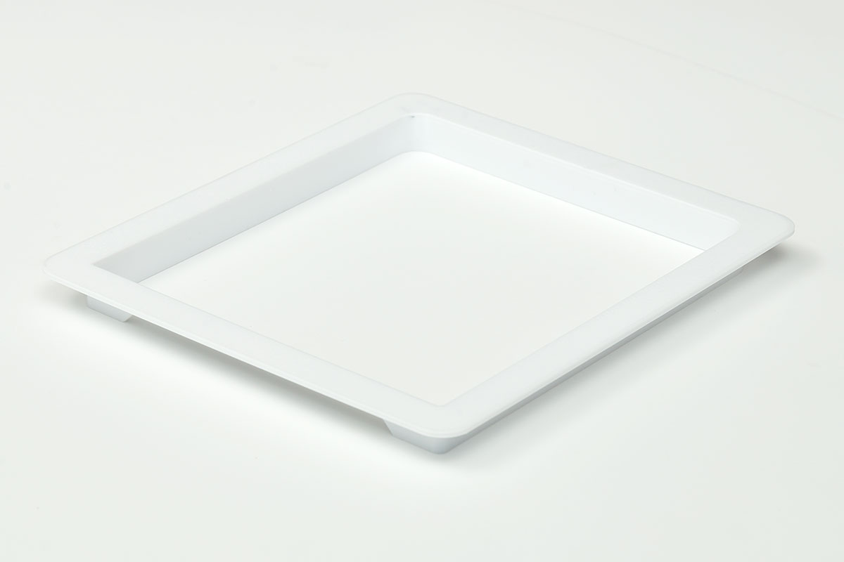
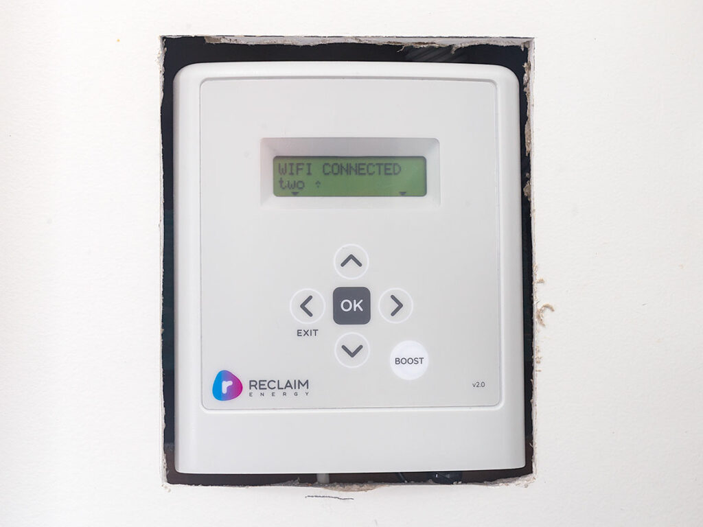
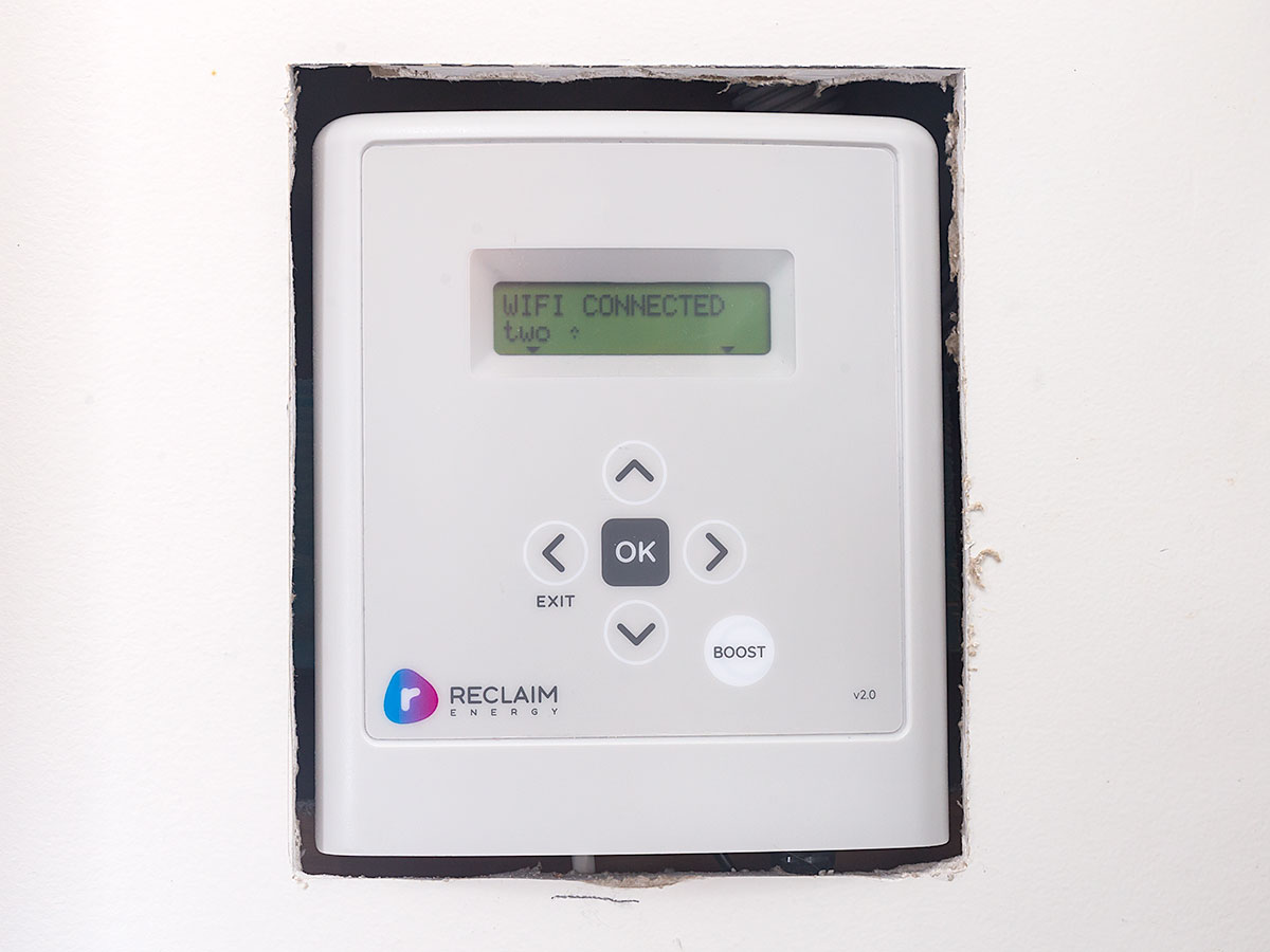
The crowning glory is the 3D-printed fascia that covers the jagged Gyprock/drywall/jib edges:
Installation process
I’m going to skip the cable-pulling component in this post, as I assume you have that sorted if you’re this far in. The focus here is more on the mounting and finishing of the controller, and some lessons learnt along the way.
Our installation was a retrofit, so some of the below will be unnecessary if you’re building afresh. (I was VERY keen to avoid patching and painting Gyprock.)
Tools
- Stud finder
- Gyprock saw
- Spirit level
- Steel rule
- Pencil
- Box knife
- Screwdriver
Consumables
- Scrap timber of varying thicknesses. These are used to pack out the cavity so the controller sits at an appropriate depth.
- Liquid Nails, or similar adhesive.
- Screws for the mounting bracket.
Step-by-step
- Use the studfinder to assess a suitable location for the controller. (If you’ve pre-cabled, you’ve presumably already done this).
- Using the 3D-printed fascia as a template, place it face-down against the wall and level it with the spirit level.
- Using your pencil draw around the inside of the hole, then remove the fascia.
- With the steel rule, measure and mark fresh lines 3mm (1/8") on the outside of the lines you’ve just drawn – but only for the sides and bottom.
- Repeat the above step for the top, marking 8mm above the original line. This is necessary as the controller slides down to lock into its T-mount, so we need to allow the clearance for it.
- With the box knife, carefully score the new outer lines. Repeat each to ensure you have a good cut through the surface paper into the body of the board.
- Now score or mark two diagonal lines across the whole opening.
- Use your Gyprock saw to cut the diagonals, then carefully punch out the four triangular pieces. A sharp tap should be all you need for them to snap along the score lines.
- Remove and discard the unwanted pieces, then clean the edges of the hole with the box knife.
- Test that the fascia fits easily into the hole, and has around 5mm of free movement vertically. If not, carefully enlarge the opening with the Gyprock saw or box knife.
- The curved front of the controller makes it a challenge to find the perfect depth for a “flush” mount, but I decided 30mm from the face of the Gyprock would do for starters.
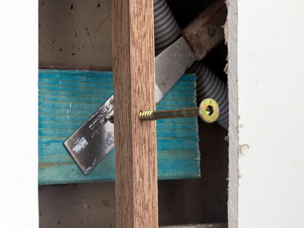
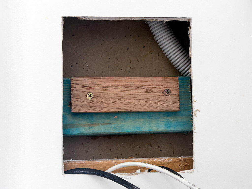
- I planned to use an offcut of 70 x 35mm pine as the primary packing piece in the hole. To help keep it in place while the glue set I prepared a temporary ‘wedge’ tool by screwing a roofing screw into a length of timber large enough to fit across the opening.
- I measured the centre of the T-mount to be approximately 85mm from the top of the opening, so that gave me a reference for roughly where in the opening the packing piece needed to go.
- I applied Liquid Nails to the rear of the pine and pressed it into the hole, wriggling it around a little to spread the glue. In this photo it is held firmly against the wall with my adjustable wedge. The metal component is a small putty knife, there to spread the pressure a little and stop the screw digging into the timber. (Don’t over-tighten this screw, as you risk cracking the Gyprock on either side of the wall.)
- Remove the wedge once the glue has dried.
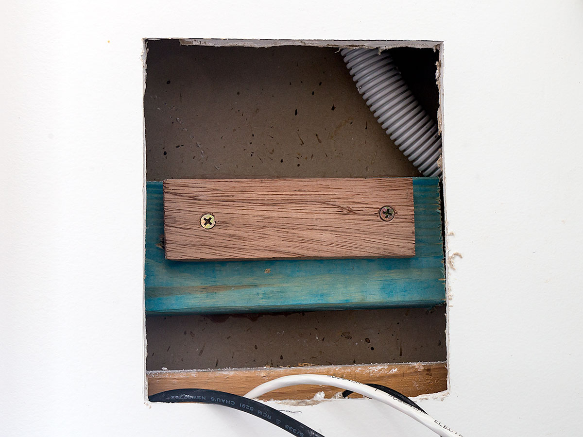
- My timber scraps box produced a suitable piece to pack the hole out to be 30mm below the surface, so that was attached with a couple of screws, being careful not to screw where the controller’s T-mount might need to be fixed. Make sure any screws you use here are fully flush so they don’t foul the T-mount to come next.
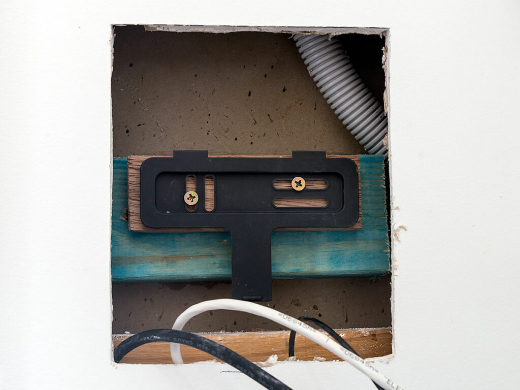
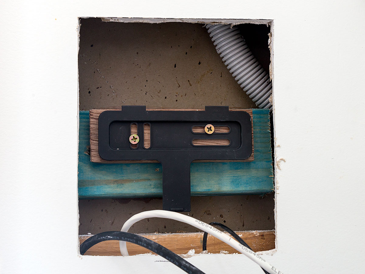
- Next came the controller’s T-mount. Its placement was basically guesswork, but I had the confidence of knowing the T-mount has four long slots, so even if I’d made a couple of bad guesses and needed to go again, there’s plenty of “forgiveness” in it. I checked it was centred in the opening horizontally, level, and its top was 65mm from the top edge before marking my initial hole placements.
- I drilled pilot holes before screwing the T-mount to the backing:
- Next is to slide the controller into position. If you’re able to navigate the controller into the hole, and it can slide and lock, you have the placement spot on.
- Apply the fascia, confirming it fits snugly and covers the Gyprock edges. If any edges are visible, you might be able to move the controller’s T-mount a little either way, and if not, you can always print another fascia with wider surrounds.
- How does it look? You don’t want it too far forward because the cable entries on the bottom need to remain concealed. Too far back and whilst the front face will be flush with the wall, you’ll have those curvy vertical sides looking weird as they roll into the wall. If you need to bring it forward a little, plastic ice-cream containers or similar make handy shims.
- If the fascia’s a little loose, a little sticky tape, gaff or even Blu-tak will help add some friction to keep it snug.

Tips & Tricks
If you’re thinking of embarking on this project, here are a few extra thoughts and bits I wanted to stress:
- If you’re working inside a cavity wall, be very careful you don’t drop anything in there, especially the T-mount! (No, just for the record, I didn’t). Some kitchen twine tied through a hole in the T-mount or your spirit level with the other end affixed to something solid will save you.
- If the rear of the cavity is *also* Gyprock, be careful with the amount of force you use when gluing or screwing. I drilled pilot holes for all the screws so the force required to screw them in was reduced. (This is why I didn’t use any nails.)
- If at Step 19 the controller doesn’t lock in easily, check the mains entry grommet isn’t fouling the bottom of the opening. If so you might need to trim a little more Gyprock out of there, or reconsider the mounting depth: it might need to sit further back in the wall.
- Rocky chose PETG rather than PLA for the fascia because the former gave a nicer surface pattern. As you can see from the main photo, the fascia doesn’t match the colour of the wall or the controller. We can’t buy PETG filament in ‘warm white’, so it looks like some spray paint will have to do.
Resources
- State Environmental Planning Policy (Exempt and Complying Development Codes) 2008 “Subdivision 23A Hot water systems” extracted above.
- The 3D-printed fascia @ printables.com
- Heat Pump Controller V2 Install Guide
- Wi-Fi Controller Consumer Brochure
Revision History
18th June 2023: this is the initial publication.
– G.


