My introduction to desktop video came back in the days of OCS 2007 R1.
It quickly occurred to me that this wasn’t going to take off until we had two things: 1) the upload bandwidth to support a decent outgoing video stream; and 2) the ability to look at the incoming video of the person you were speaking with, whilst at the same time staring directly down the lens of the camera.
Thankfully the NBN has delivered on the first component here in Oz, but technology has so far failed to come through on the second, and so most of us participate in video calls with the participants all looking off to the side while you’re talking to them.
I theorised that the fix would be when a screen vendor figured out how to place a camera mid-screen directly behind the glass. I remember saying I’d race out and buy two the day they hit the market (so my two monitors matched).
The hubby has more recently suggested it’ll be delivered via algorithm instead. There will be a camera in the four corners of the screen and digital magic will stitch together a coherent moving image of you with eyes pointing ‘naturally’ at the camera.
I saw on Twitter only yesterday that Microsoft has apparently delivered something similar in the Surface Pro X with a feature they’re calling "Eye Contact".
Roll forward to 2020 though, and with lots of us now working from home and participating in non-stop meetings, I thought it was time to make matters into my own hands.
The Concept
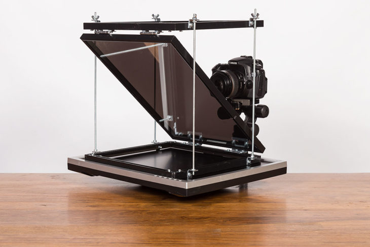
The idea behind the autocue is a fairly simple one. All you need is a piece of front-mirrored glass at 45° to you, with a monitor below (or above!) it and the camera behind. The camera only captures you, and yet all you see is the image on the monitor. Wikipedia describes it well.
Having sourced myself some glass, I needed a way of housing the assembly, and the picture frames made from relatively cheap aluminium extrusion struck me as ideal, especially given aluminium is light, thin, and easily worked.

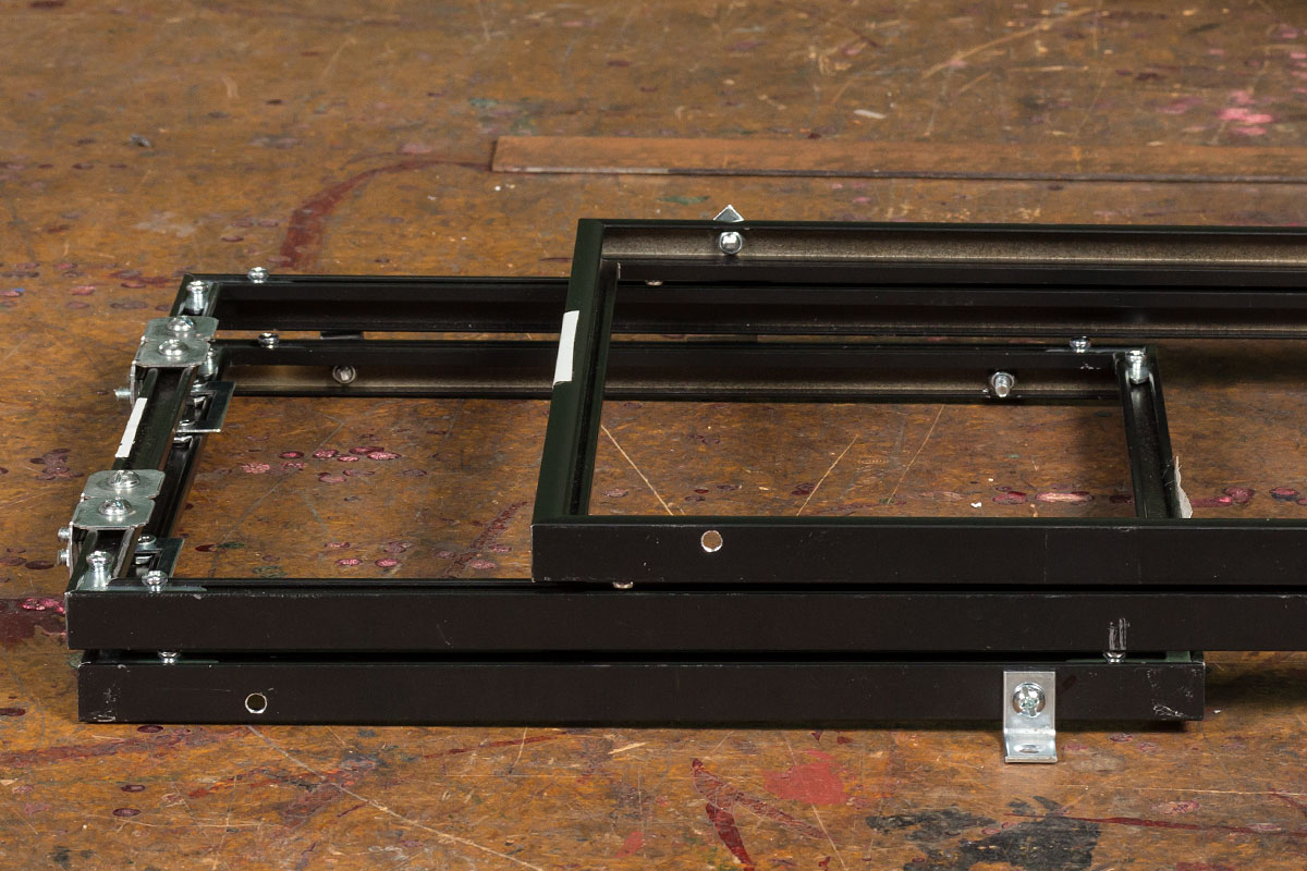
My autocue comprises three such frames bolted together with hinges into a "Z" fold arrangement. The diagonal frame holds the mirror, the top and bottom frames are for mounting/stability, and the hinges allow you to fold the autocue flat for storage or transport.
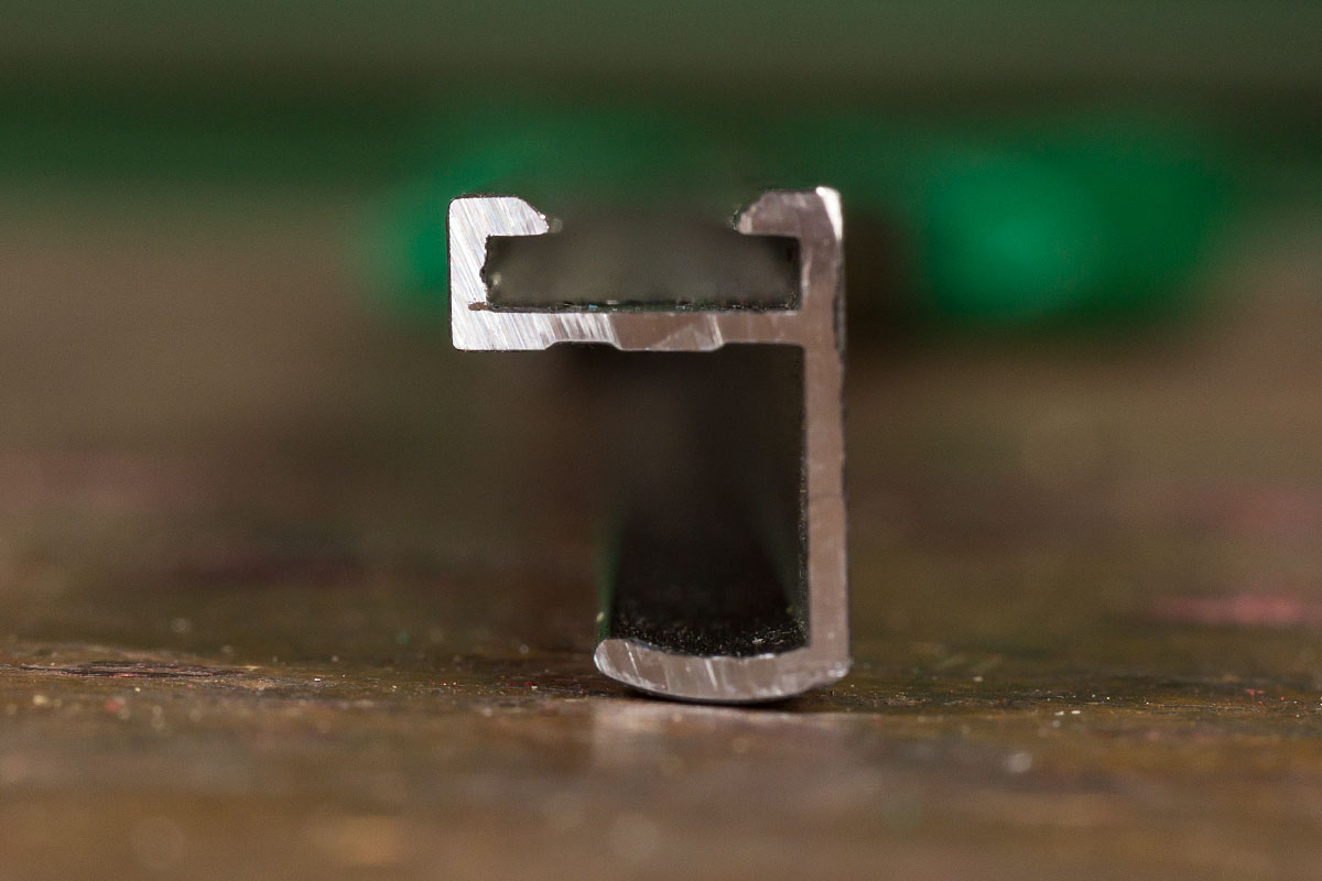
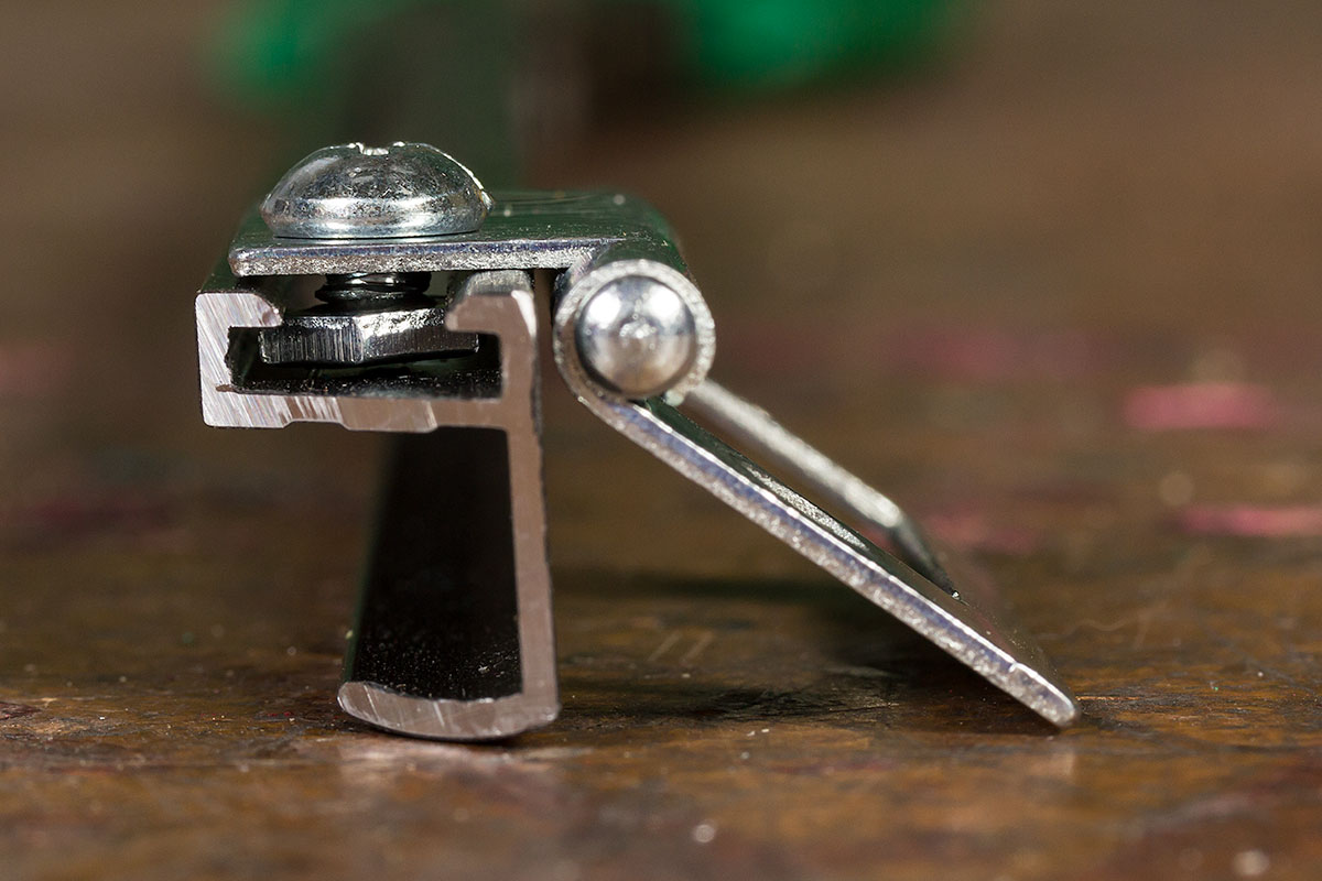
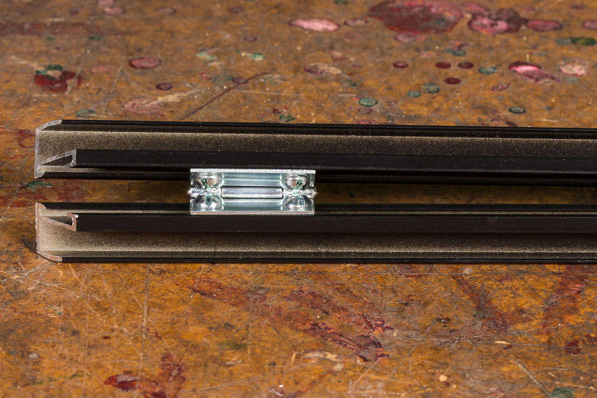
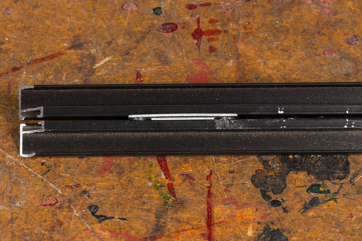
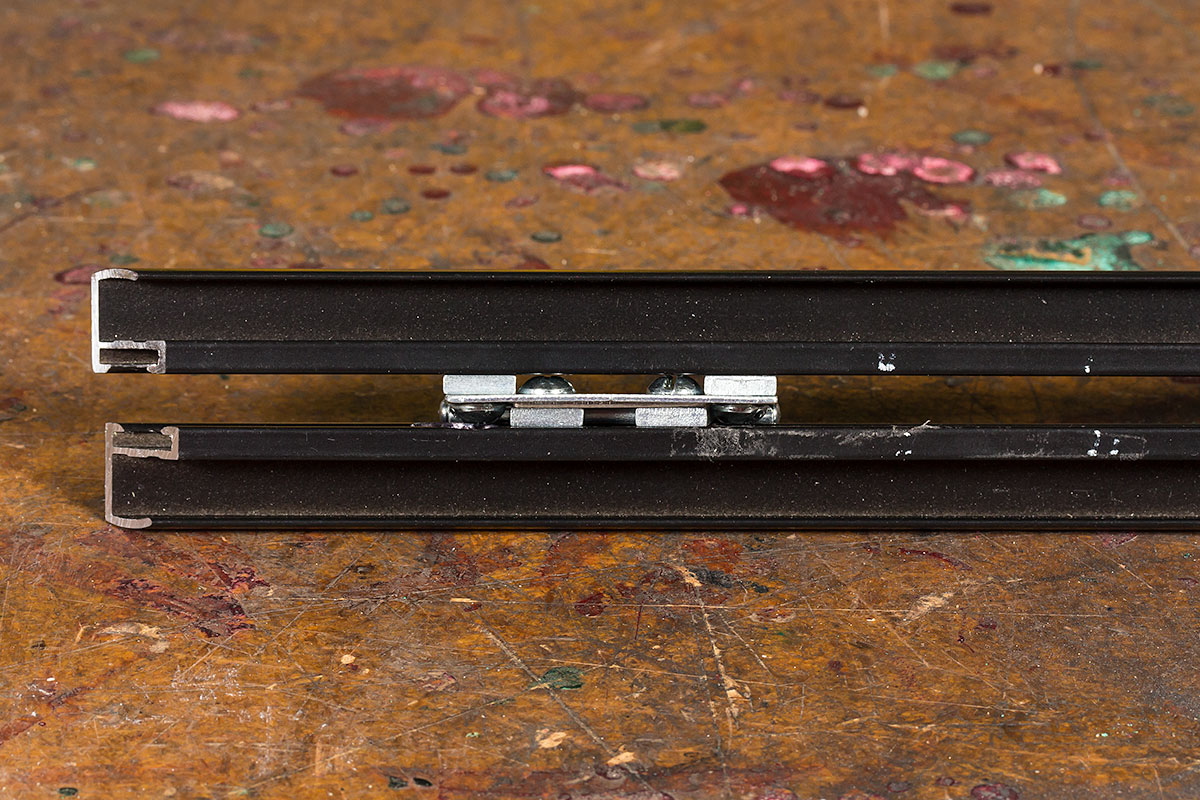
These end-on views of the extrusion show how little room there is for movement in the bolt shafts, and for the nuts that clamp the hinges to the frame.
In reality I think your chances of sourcing bolts EXACTLY the right length are next to nothing, so be prepared to hacksaw, file and/or grind bolts to the correct lengths.
The Design
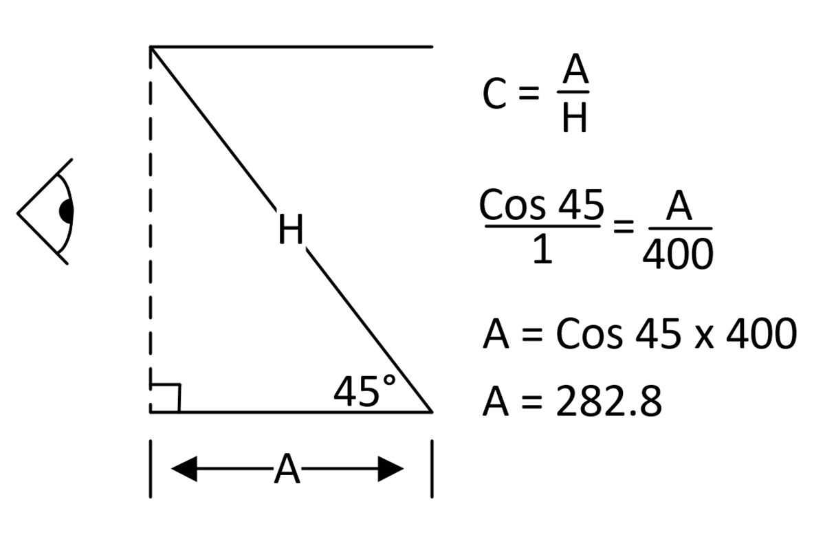
The autocue described herein came together over a few months here in Sydney, Australia. I started with a purely arbitrary size of 300x400mm (12×16") for the mirror and went from there.
Some schoolyard trigonometry showed that with a 300x400mm mirror at 45° to the horizontal, the matching "glass" in the top and bottom frames would be 300x282mm.
I standardised on 3/16" [British Standard] Whitworth nuts and bolts as those are fairly common here, but you can choose whatever works for you.
I made SEVERAL mistakes in the process, and I’ll share those with you as I step through the build below.
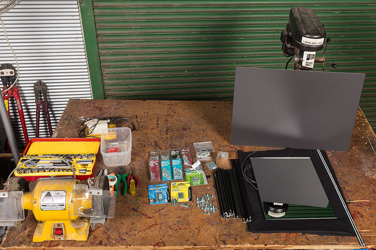
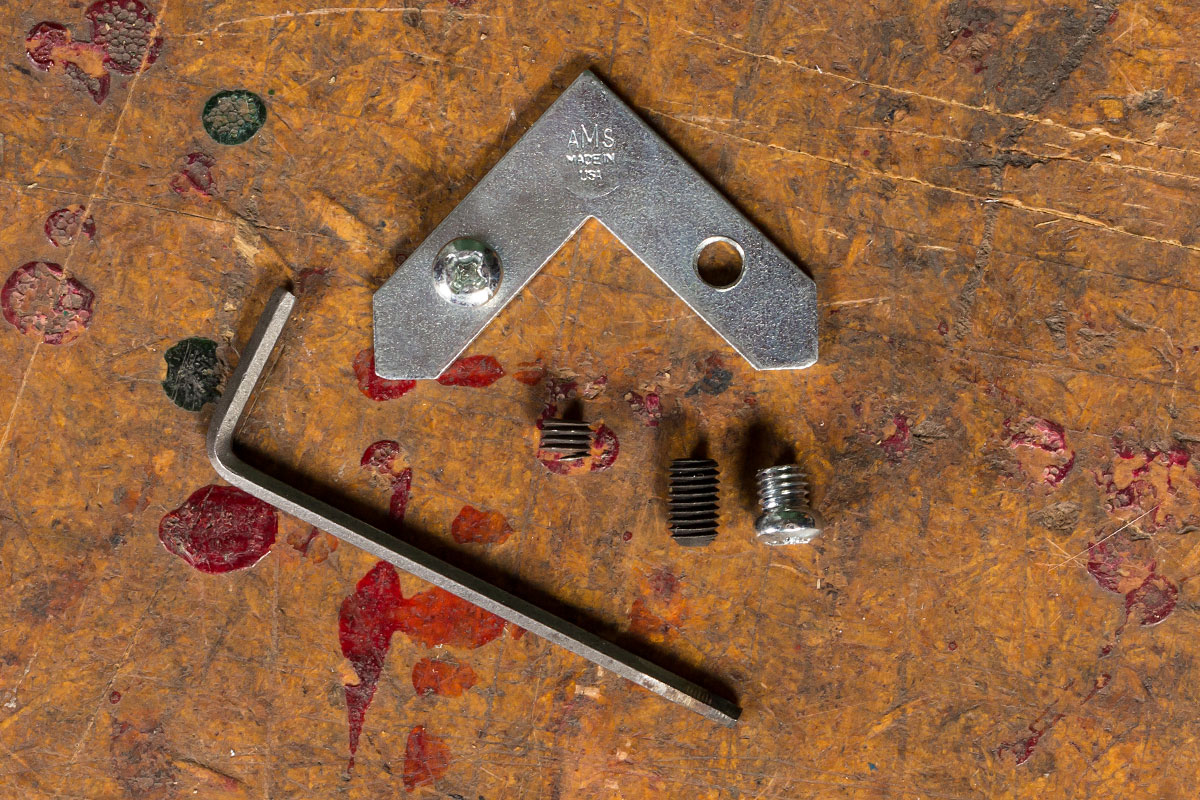
Shopping List
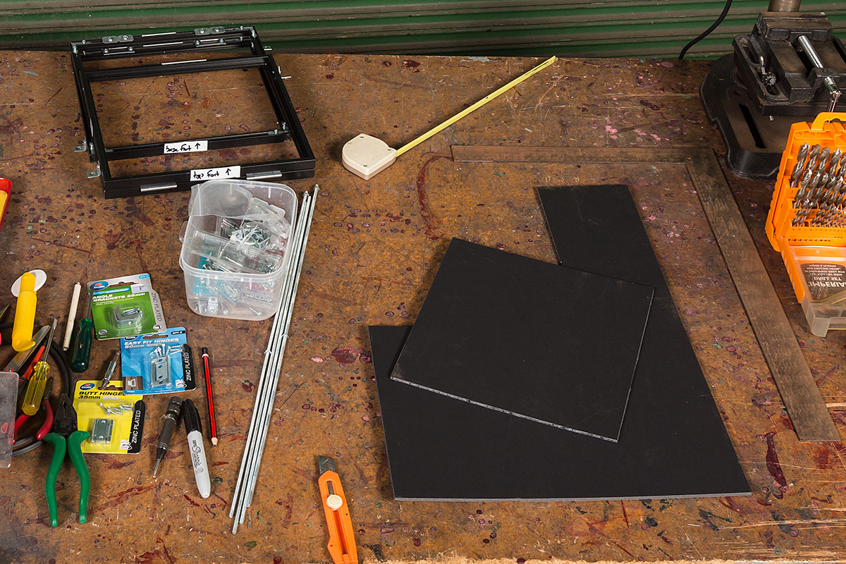
Here are all the bits laid out on the bench. Click on the photo for an enlarged version and a better look at it all.
| Qty | Item | Notes |
|---|---|---|
| 1 | front-surfaced mirror | |
| 1 | aluminium picture frame | made to fit the mirror |
| 2 | aluminium picture frames | these are for the top and bottom |
| 4 lengths | 3/16" threaded rod | at least 34cm (13") long |
| 4 | "easy fit" hinges | preferably black |
| 2 | pieces of light gal / sheet aluminium | for the "outer hinge" assembly – see text |
| 8 | 20mm angle brackets | |
| 24 | 3/16" round head bolts | |
| 4 | 3/16" countersunk head bolts | I’m not proud of this |
| 28 | 3/16" low-profile nuts | square head if you can – see text |
| 8 | 1/4" nuts | approx 3mm (1/8") thick, these are used as spacers |
| 8 | 3/16" nylon lock nuts | |
| 4 | 3/16" wing-nuts | |
| length | heavy black material | something like a towel would be great |
| 1 piece | dark art-board | |
| 1.4m length | wedge rubber | holds the glass in the frame |
| A tube | Locktite, or some glue |
Cost
The mirror cost me $AUD100 ($US72 / €61) and the frames $AUD120 ($US86 / €73). The rest of the hardware was fairly cheap, so I’d say the whole lot set me back around $AUD270 ($US194 / €164).
Tools
- screwdrivers
- tape-measure or rule(r)
- socket set (optional but very handy for holding/driving the nuts)
- shifter/spanners
- white tape & permanent marker (for labelling all the pieces)
- hacksaw
- bastard (coarse) file
- points file or similar fine-edged file (for restoring damaged threads)
- boltcutters (or the hacksaw again)
- bench vice (if you’re trimming bolts with the hacksaw or file)
- hole punch
- electric drill and bits
- bench grinder (GREAT for trimming bolts to length) + safety glasses and earmuffs
- spirit level
- a spline roller will help with the wedge rubber
The Build
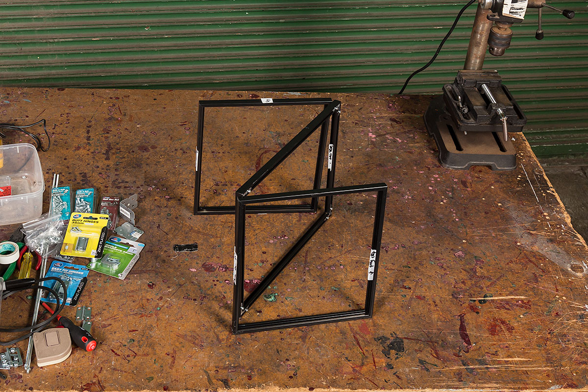
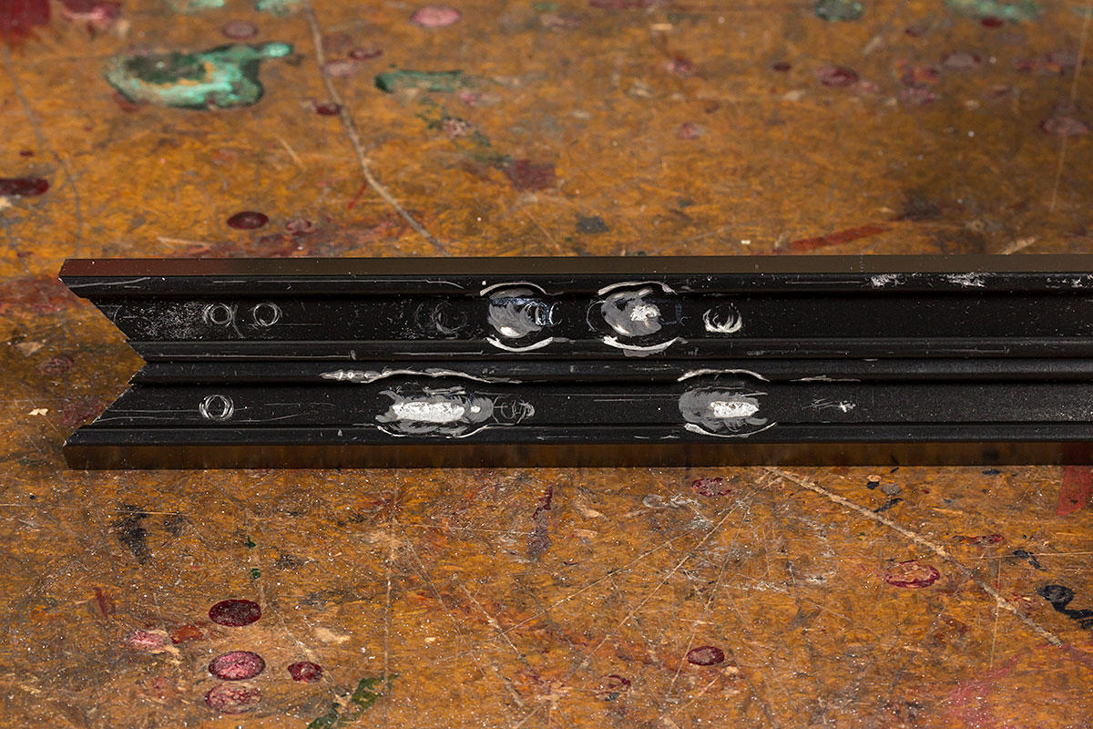
I first assembled the three frames and sat them in position on their side, then applied tape to all the edges and marked their location. The need for the tape became apparent after accidentally assembling one frame as square and wondering why things didn’t line up. You’ll see images with tape marked “S” (for “side”), and others more descriptively like “top rear” and an arrow pointing up (although yes the arrow’s probably a little redundant given I don’t usually write upside-down).
As shown in the end-on image of the extrusion (above), the frames have a “dress” face at the front and a rear channel where the corner pieces are inserted.
I decided the top frame would sit facing upwards and the mirror would have its dress face forward. That results in a neat “inner hinge” at the top of the autocue, leaving a less elegant wrap-around “outer hinge” on the bottom at the rear.
Mistake #1:A decision I’ve come to regret is having the bottom frame facing down. The idea at the time was that its face would be more gentle to the monitor on which it sat, but in retrospect, I should have just used rubber feet screwed into the rear channel, which would have left the dress surface visible to the user.
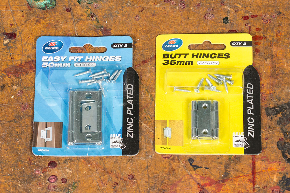
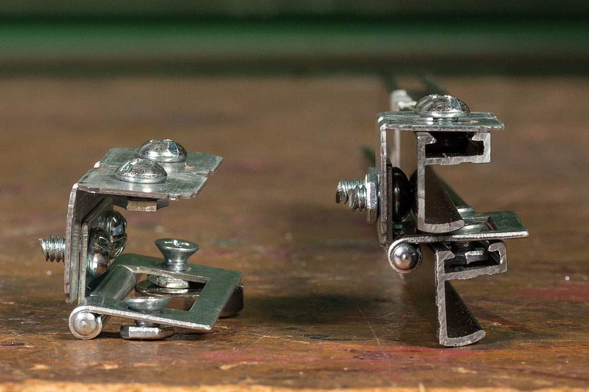
Mistake #2:My second mistake was initially choosing “butt hinges”. The problem you see here is that the heads of the bolts foul each other, so the autocue won’t fold closed:
Cue the return visit to the hardware store for four “easy fit hinges”, with their holes inline.
These hinges don’t fully address the problem, as the heads now foul the aluminium frame itself:

Here I used my drill press to ‘widen’ the channel to allow the heads to recess, and finished with the Supertool (my 80s vintage precursor to the Dremel, but still going strong). It’s not all that pretty, but no-one’s going to see it. Use your Sharpie/Outline texta to colour in the worst of it.
Don’t forget the other side – there are two hinges here.

MUCH better!
With the top hinges sorted, I then moved my attention to the other end of the mirror’s frame. This needed to be a kind of “wrap-around” assembly, as it needed to join the upper side of the mirror frame (when packed flat) to the upper side of the base.
Here’s an image of the rear hinge assembly. (Don’t forget you need two of these). I had some pieces of gal bracket handy, but thin right-angle aluminium would work just as well.
You’ll see I’ve also committed the heinous crime of using countersunk head bolts into the lower frame. That was an “of necessity” decision, all to do with clearance and allowing the autocue to pack flat. Were I to build another autocue, I’d more carefully drill the angle-bracket to introduce some additional clearance, allowing the use of the correct bolts. (As confessed in Mistake #1, I would also flip the lower frame, necessitating a longer bracket).
With the hinges complete I was on the home stretch, and assembled the frames only to hit another show-stopper:
Mistake #3:The top and mirror frames STILL won’t pack flat, as the screws in the right-angle brackets that hold the frames together now foul each other. AAARGH! This was MOST unexpected:

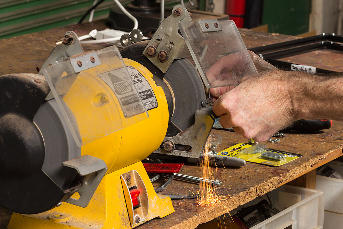
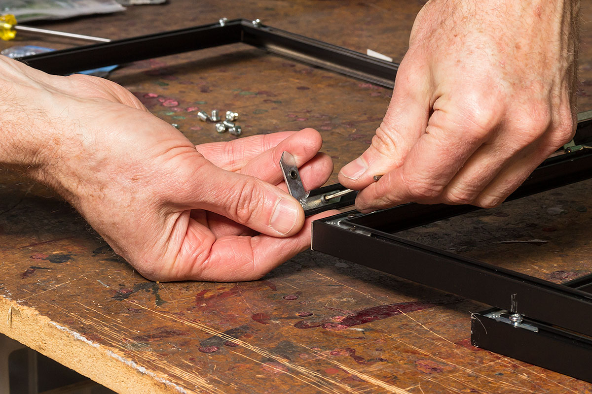
The approach I took here is not for the faint-hearted, but with Sydney’s ultimate nut, bolt and screw shop walking distance from home I went in search of grub screws to replace the frame’s screws.
These turned out to be still too long – still fouling each other – and so I pressed the grinder into service to grind eight of them down to the tiny size required to force the brackets into the channel whilst still remaining under the channel’s height.
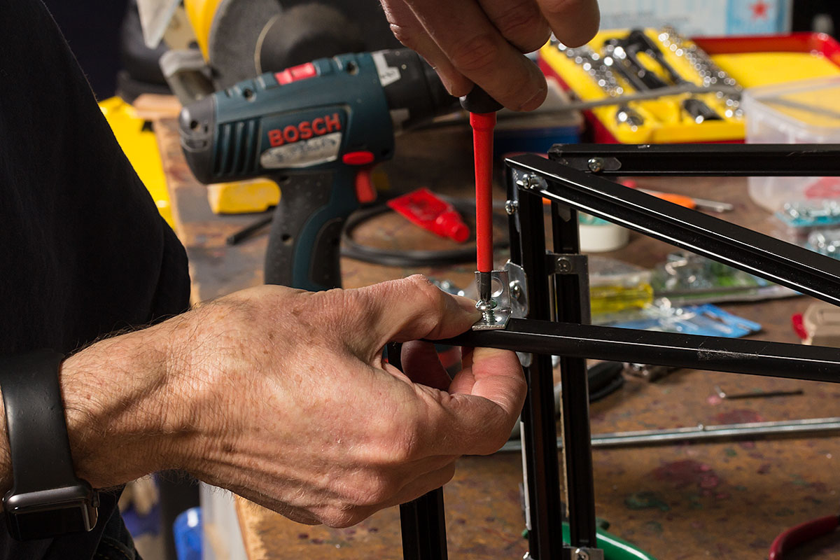
With the frames assembled it’s time to mount the angle-brackets for the threaded rods.
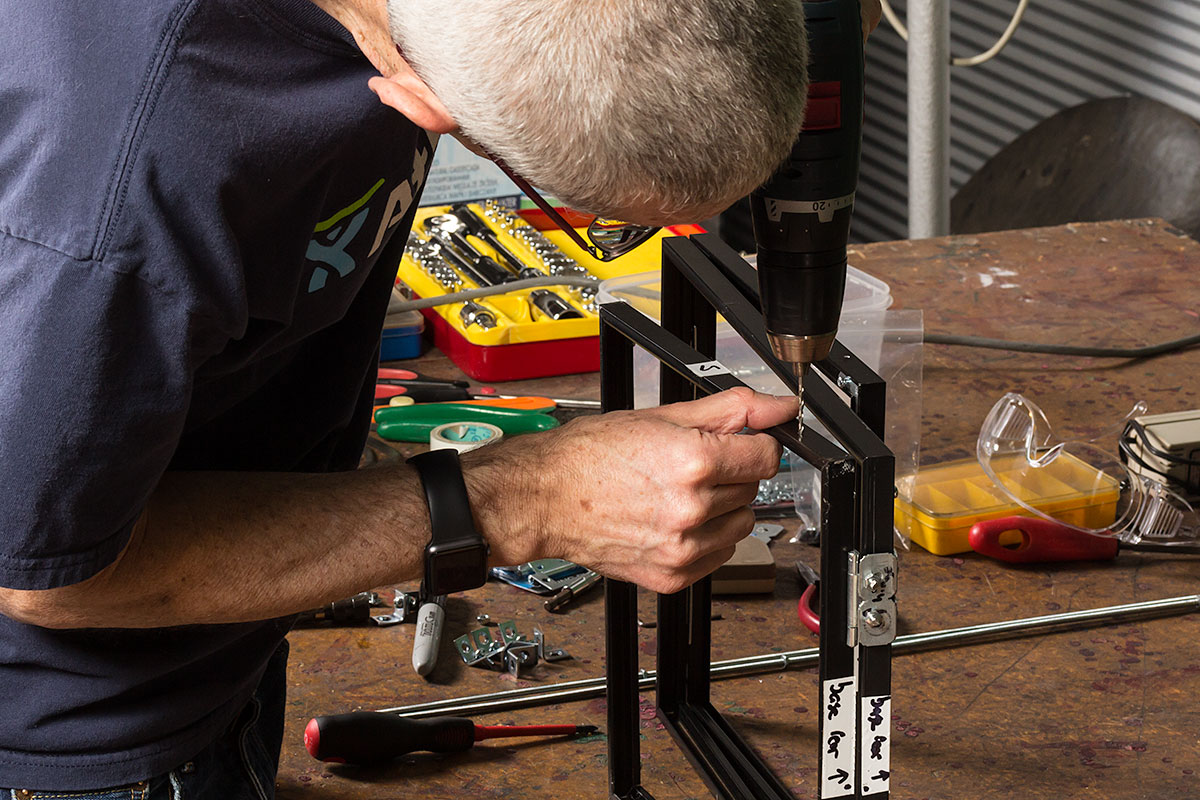
I drilled a pair of 3/16″ holes in each side of the upper and lower frames, ~4.5cm (just under 2″) in from the ends. Make sure they’re offset, NOT centred. You want the hole to be in the middle of the channel that the glass would normally live in, otherwise you might have problems getting the nut in (without more butchery / precision aluminium surgery). And remember these are the upper and lower frames, so this channel is free for us to use.
Affix the angle brackets to these pieces using the nylon lock nuts, but don’t tighten them fully at this stage. Four will want to be fixed and four will want to swivel. The ones that are free to move will let you pack the autocue flat with one end of the rods made captive.
At this point I cut the art-board to size and inserted it into the top frame. The screws and nylon nuts press into it slightly, but that’s acceptable. This piece of art-board adds stability to the frame and contributes to keeping light out of the camera’s realm.
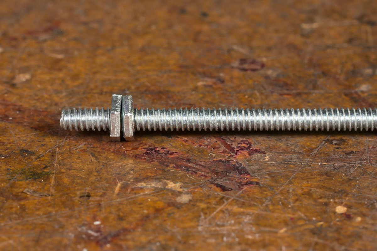
Now thread two nuts onto one end of each of the four threaded rods. Wind them no more than 1cm (1/2″) and use the shifter and socket (or pliers) to firmly lock them together.
Thread two more nuts onto the other end of each rod. They should be around 30cm (12″) from the “locknut” pair you added in the previous step. Don’t lock these off yet though.
Assemble the autocue by first threading the rod *up* through the brackets in the upper frame, so that the excess is in the air, and the locked-off nuts are sitting in the lower frame.

Use the spirit level to level it all up, adjusting the loose nuts now under the top frame until it’s all level and the diagonal frame is at the correct angle.
I used the giant tee-square (visible to the right of the autocue in the image above) to get a rough 45° angle. I figured the glass will be at 45° if the upper and lower edges touch the vertical of the square. *Do* leave yourself some wriggle-room prior to the chopping step coming up.
Before you continue, thread a wing-nut onto the top of each rod. I’ll tell you why in a sec.
Use your boltcutters to remove the excess:
(A builder friend of mine refers to boltcutters as the "master key". Whatever could he mean?)
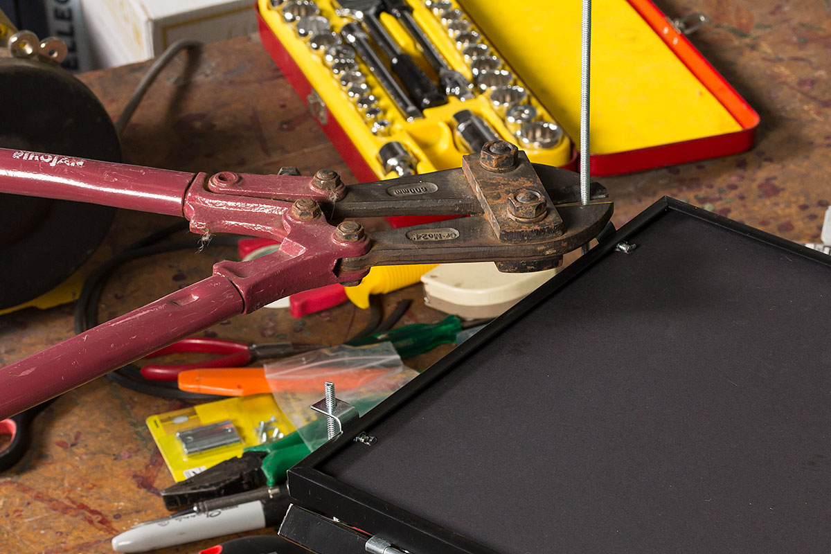
If you don’t have bolt-cutters or a heavy pair of pliers, remove the rods – one at a time if you can – and hacksaw the excess off, then return them to the assembly.
Now for a trick: slowly and carefully unscrew and re-screw the wingnuts, going all the way to the end, but trying NOT to lose them off the end. Doing this helps restore the thread damaged by the boltcutters. The more times you can do this the better, as it will pay off when you try to thread them on in the future. If you find it still difficult to get the wingnuts started on the rod, I have a small square file that I use in circumstances like these, and a points file also works well.
The final rod decision I’ll leave to you. If you decide to leave the rods permanently affixed (so you don’t lose them), I think the best approach is to lock the top of the front rods and the bottom of the rear ones – which happen to be those closest to the hinges and the diagonal mirror. This means the autocue will pack flat with no protruding bits of rod. If you go with this approach, flip the front ones and apply another pair of nuts and lock them off to make the rod captive on the TOP angle brackets. Be careful here to make sure the adjustable section won’t protrude too far through the front angle bracket and scratch the screen. (You’ll see in the images the brackets all face away from the screen for this reason.)
With the frame all levelled up, remove the rods, lay it out flat, and remove two of the screws holding the mirror’s frame together.
Carefully slide the glass in, taking care not to go anything that might scratch the delicate mirrored surface, then reassemble the frame.
Starting from one corner, and with the mirror’s dress face down, insert the wedge rubber and work it around all four sides, taking care at the corners.

I have a little wheel tool (spline roller) bought for a flyscreen job, and this made the task much easier.
With that done, stand the autocue up and marvel at your creation.

Hindsight’s a bitch
While documenting the build for this post it became apparent there were some steps for which we didn’t have accompanying images.
In a do-over to shoot those I realised I could have saved myself a LOT of trouble had I taken a different approach in responding to Mistake #2 (the butt hinges).
If I’d only added some spacers between the hinge arms and the frames, I would have not only saved myself the hassle of notching out the aluminium to recess the bolt heads, but ALSO the whole grub screw saga.
Here’s a hinge with a fresh set of 15mm bolts, and a 1/4" nut doing duty as a spacer. The bolts on the right I’ve already trimmed roughly with the boltcutters:

Here they are after having been ground down:
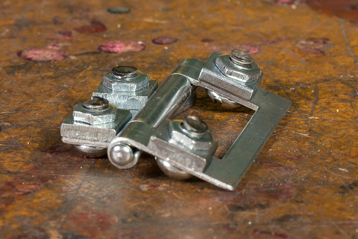
And here they are in-situ, again showing the hinge closing nicely, albeit with a little more of an air gap than before.
… and here’s the unit all closed up, original corner screws reinstated and nicely avoiding each other.
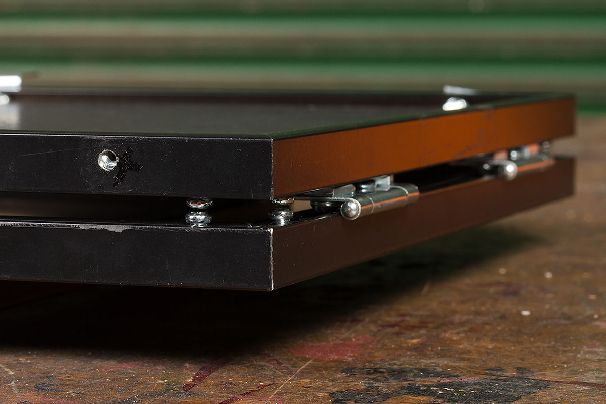
TADA!

The only finishing touch it needs is a shroud over the top section to keep light away from the camera. I’m hoping to impose upon a friend with a sewing machine to knock up a suitable shroud. If you go down this path, consider making it over-sized, add some handles, and you have a carry-case!
Where to next?
The autocue is only one part of the solution to engaging video calls. Obviously you’ll need a camera, and you might not have realised you’re also going to need some additional lighting, because the mirror results in a *significant* loss of light – around 4 f-stops.
You also need to be able to flip the image on the monitor, and sadly that’s not one of the built-in Windows options. I use the utility ultramon, and I know there are dedicated hardware alternatives too.
Check out my post “Inject OBS Studio into Microsoft Teams” for more tips and traps.
Credits
Thanks to Seamus @ framemart.com.au for supplying the frames, and as always Rocky for the photos.
Revision History
24th August 2020: this is the initial publication.
– G.


